Quantcast
Channel: UC Corner
Viewing all 54 articles
Browse latest View live

Perl Script For Subtitle Conversion

$
0
0
This has nothing to do with Unified Communications.  But I don't have another blog for video editing.  Thus I post it here for anyone who needs it.

I've been using SVDTS plugin for Sony Vegas Pro to export the timecode from AVCHD video (.mts) to a subtitle file.  Having the timecode as a subtitle gives you the flexibility to turn it on or off at will.  If the timecode was "burned in", it'll display on the screen all the time.

With subtitle on:


With subtitle off:

However, the SVDTS plugin exports subtitle in Sony DVD Architect format, which is not a recognized format for other software (such as Corel VideoStudio, Adobe Premiere Pro, etc.).  It'd be better if it was in SubRip (.srt) format, which is more popular and well recognized.

DVD Architect format:

SubRip format:

Perl is the perfect tool for this kind of task:
if ($#ARGV != 1) {
  print "\nUsage: perl sub2srt.pl sub_filename srt_filename\n";
  exit;
 }

if (-e $ARGV[1]) {
  print "\nFile $ARGV[1] already exists!\n";
 }

open (SubFile, "< $ARGV[0]") or die "Couldn't open $ARGV[0] for reading: $!\n";
open (SrtFile, "> $ARGV[1]") or die "Couldn't open $ARGV[1] for writing: $!\n";

my($n) = 1;    #SRT subtitle index

while () {
  next if /^$/;    #Skip blank lines
  my($line) = $_;
  my($start) = substr($line, 5, 8);
  my($end) = substr($line, 17, 8);
  my($content) = substr($line, 29);
  print SrtFile "$n\n";
  print SrtFile "$start,000 --> $end,000\n";
  print SrtFile "$content\n";
  $n++;
 }

close (SubFile);
close (SrtFile);

 Save above codes as sub2srt.pl.  The command line syntax is "perl sub2srt.pl myfile.sub myfile.srt".


Enterprise Licence Manager

$
0
0
Since from UCM 9.0, Cisco introduced ELM (Enterprise License Manager).  Instead of putting license files on UCM, CUC servers, now you put license files on a "License Server" (ELM).


This is similar to some other software manufacturers such as Microsoft's KMS, VMware's license server, etc.

The advantages are obvious:

  • Have a centralized location to manage licenses for multiple servers/products (UCM, CUC, etc.)
  • Having a single license pool makes it easier to allocate/relocate license.  For example, you decommissioned a UCM server and installed a new one.  In the past, you need to open a Cisco case to "rehost" the license (because of the change of license MAC).  Now you may do it yourself with ELM.
ELM comes with the UCM9 installation DVD.  You may install it as a standalone server or co-resident with UCM.  In a real enterprise environment, it makes sense to have a standalone ELM server.  So the ELM was not affected if you had to reinstall the UCM.


Please note that workflow has changed with this new architecture.  Before, you need the "license MAC" of the UCM server when requesting license.  Now, you need the "license request" of the ELM server.  With this workflow, you may request license without knowing the UCM's MAC address.

"license request" is the signature of ELM server.  Cisco uses this signature to encrypt the license file so it can only be decrypted by the requesting ELM (signature owner).


The request (signature) is encoded in Base64 format.  You may decode it with any Base64 decoder.


Don't be confused if you're still seeing scrambled characters after decoding.  As seen from screenshot above, the request consists of Cisco proprietary info (such as server ID) and a standard X.509 CSR.  Proprietary info are in binary format thus you won't be able to read it in plain text.  CSR is encoded in Base64 (yes, Base64 in Base64).  You may further decode the CSR if you're interested.  Just copy the text portion between "-----BEGIN CERTIFICATE REQUEST----- " and "-----END CERTIFICATE REQUEST----- ", then paste it into a CSR decoder.


Interesting enough, ELM uses PostgreSQL instead of UCM's Informix.  Use "su - postgres" to switch to postgres user so you can have access to the database.

In case you're not familiar with PostgreSQL, here are some commands you may use to get started:

psql : PostgreSQL command line interface
\l : List databases
\c : Connect to a database
\d : List tables
\d: Describe a table


You may use standard SQL statement to view or change the data in tables.  You may put the SQL statement in one line or multiple lines.  Semicolon(;) is a special character to trigger the execution of the SQL statement.  You may put the semicolon at the same line of the SQL statement or a different line.


is the same as


Correction to the Cisco UC rooting process

$
0
0
I got a lot of feedback regarding the problem after rooting Cisco UC products (CUCM/UCCX, etc.).  The symptom was that every service is in [STARTING] state and you get 'Database Communication Error' while trying to log into the GUI (as the 'A Cisco DB' service was not able to start).

It's strange as I never ran into any problem.  I reviewed the process today and ran some tests.  I think I found the problem.  There's an unnecessary section in the instructions:

For version 8.6 or later, Cisco use SeLinux for additional security.  You need the following:

vi /etc/pam.d/su, comment the following:
    #auth   sufficient      /lib/security/$ISA/pam_rootok.so debug
    #auth   required        /lib/security/$ISA/pam_wheel.so group=priviledged_grp


 This section was added to the blog based on a reader's feedback.  I didn't verify it myself and thought it wouldn't do any harm even if it's unnecessary.

Evidently, this unnecessary step broke the system.  If you already performed this, you may undo it by removing the # signs. So the two lines should read like this:

auth    sufficient      /lib/security/$ISA/pam_rootok.so debug
auth    required        /lib/security/$ISA/pam_wheel.so group=priviledged_grp

Reboot the system after making the changes.  View service status with command 'utils service list page'.  You should see 'A Cisco DB' service is [STARTED].  Wait for a while, other services should be in [STARTED] state.

I've removed the section from original post.  Sorry for the inconvenience caused.

Running UC Labs on a laptop

$
0
0
Not everyone has the luxury of running a Cisco UCS server at home.  Even if you do, it's a little bit heavy to drag the UCS around.  It would be convenient to have the UC lab built on your laptop.

I myself am using VMware Workstation 9.0.2 on a ThinkPad T430 with 16G RAM/1TB HDD.  Some of the laptops (such as ThinkPad W-series) allow you go for 32G RAM, which is really helpful if you need to run multiple boxes (such as UCM, UCCX, UCXN, CUPS, CER, AD) at the same time.

Personally, I prefer creating the VM spec myself instead of importing the OVA file from Cisco.  Some of the spec in OVA doesn't make sense in a lab environment.  (For example, what good would it do to have 2 vCPU in the VM while you're running it on a laptop?)

For the VM hard drive, I always use thin provisioning and use one single file.

For VM network, I'd prefer "host-only network" unless you have other external components need to talk to the UC lab.

Depending on your UC version, you might run into strange problems that the UC box can't ping anywhere in "host-only network" (not even the VMs in the same network).  For example, I ran into this problem with UCCX 8.5.1 while UCM 8.6.2 was fine.  The solution is to upgrade VMTools on the UC box.

In later versions, NTP and DNS become mandatory.  You may set up those on your Windows 7 desktop (your host OS), so you don't need a dedicated Windows server to do that.  For NTP, it's built in Win7.  Just follow the procedure on  http://htluo.blogspot.com/2009/02/ntp-network-time-protocol.html.  For DNS, you may google for some freeware or shareware.

In a "host-only network", you have the option to have a host adapter connects to the network.  So you may connect to the UC boxes from your host OS (e.g. run CIPC from your Win7 desktop).  By default, the "host-only network" is in the 192.168.130.0 network (or a random class-C in the 192.168 range).  You may change it.  You may also change the host adapter (default is VMnet1) IP address.  If the change didn't seem to take effect, please check the 'Advanced' button in the TCP/IP bindings.  You might have multiple IP addresses bound to the VMnet1 adapter.

IOU Web

$
0
0
Lately I had to recreate a MPLS network.  I used to use GNS3 as it's user friendly and can use vanilla IOS (i.e. you may download IOS from cisco.com and throw it into GNS3).  GNS3 can also emulate other devices such as PIX, ASA, IDS, Juniper, and even a host (with simple ping command).

GNS3 is almost perfect except for performance.  With a couple routers turned on, GNS3 is pegging about 90% of the CPU. So I look for alternatives.

IOU (IOS on Unix) is a Cisco-Internal-Only tool that emulate IOS devices.  It has quite a few drawbacks:

  • Cisco Internal Only
  • Has to run proprietary IOS
  • Not user friendly - You'll have to build your network topology from a text editor instead of drag-and-drop.  You'll have to do a lot of thing from Unix/Linux command line.
However, IOU has one, big advantage - performance.  You may run tens (if not hundreds) of routers at the same time with minimal CPU/memory consumption.

Drawback #1 and #2 are no longer problems in the era of Google.  For #3, Andrea Dainese built "IOU Web" - a web interface to manage labs on IOU.

Just think of IOU as a back end process running on Linux.  'IOU Web' is the front end interface.  Like "CallManager Service" is the back end and "CCMAdmin web" is the front end.

One other thing I like about IOU Web is - you may make your own 'clickable' network diagrams.  You make your own network diagram, save it as jpg, make the routers/switches clickable.  When you click on a router on the drawing, it'll open up a telnet session to that router.

You may also copy the lab content (in rich format) and paste it into the 'Description' tab.  Then edit it the way you like.  Very convenient on building your home lab (and carry it anywhere you go).


Build a $30 Wireless Lab

$
0
0
One of the recent project has quite a lot wireless LAN stuff.  So I feel the urge to build a home lab.

To build a wireless LAN lab, you need at least two things - a WLC (Wireless LAN Controller) and some compatible APs (Access Points).

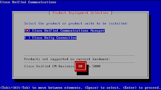
WLC was easy since you may download the virtual WLC (vWLC) software from cisco.com and throw it on VMware.

It's not that easy when it comes to AP.  There are so many different models from Cisco.  I want the one that I can test most (if not all) the features with, while not costing me a fortune.  After some research (both on cisco.com and eBay.com), I decided 1242AG is the one.  This is a not-so-old AP that has 802.11a/b/g frequency and support many enterprise WLAN features (such as FlexConnect).  Most importantly, it's pretty affordable.  I got two for $30 (free shipping) from eBay.  I ordered two in case I need to test the "roaming" feature.

It looks like this:


Two things to be aware of:
1) Make sure to order one with antennas.  Otherwise it'll cost you some extra bucks.
2) They are mostly POE.  So you'll need a POE switch or power adapter.  You may get a cheap POE switch for less than $20.  But those switch won't support VLAN trunking, just FYI.

Luckily I still have my 3750G POE switch sitting around (from my CCIE voice lab).  Now I have to design the network.

In case you don't know, in real-life enterprise WLAN, they usually use DHCP option 43 to deliver the WLC IP address to APs.  I'd like to do the same in my lab.

But my Linksys router doesn't have the capability to configure DHCP options.  Thus I need to set up a another DHCP server.  How may I set up a secondary DHCP server while not interfering with the primary one?  The answer is to put them into different VLAN/subnets.

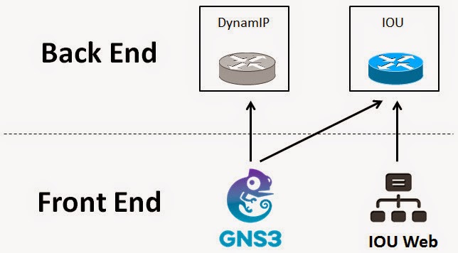
Here's my network design:


My Linksys home router connects to 3750 switch VLAN 1.  The two APs connect to 3750 switch VLAN 3.

3750 configuration:
ip dhcp excluded-address 192.168.3.1 192.168.3.10
!
ip dhcp pool Wireless-Lab
   network 192.168.3.0 255.255.255.0
   default-router 192.168.3.1
   option 43 hex f104.c0a8.0216
!
interface Vlan1
 ip address 192.168.2.1 255.255.255.0
!
interface Vlan3
 ip address 192.168.3.1 255.255.255.0
!
ip route 0.0.0.0 0.0.0.0 192.168.2.100
!
interface GigabitEthernet1/0/1
 description Linksys Router
!
interface GigabitEthernet1/0/2
 description AP-1
 switchport access vlan 3
!
interface GigabitEthernet1/0/3
 description AP-2
 switchport access vlan 3
Linksys configuraiton:

Now you should be able to ping from home PC (VLAN1) to VLAN 3 and vice versa.

On the vWLC virtual machine, I set the NIC to bridge network so I can configure a static IP in my home network segment (I used 192.168.2.22).

Now you should be able to open a web page to the vWLC management portal.  Also, you should be able to ping from the vWLC (192.168.2.22) to VLAN3 (192.168.3.1) and vice versa.

In theory, when I plug the APs to the switch, they should:
1) Power up
2) Get their IP address and the vWLC's IP address (via option 43 from DHCP)
3) Join the WLC

Well, not surprisingly, they didn't work as desired.  (if they did, there will be not much value for CCIEs)

As a WLAN newbie, I went for documents, turned on debug, capture error messages, post questions on Cisco support forum.  After spent quite some time on troubleshooting, I was advised to upgrade the IOS (does that sound familiar?)

There are many different software, tools and procedures regarding AP upgrade:
  • Autonomous vs. Lightwight vs. Recovery
  • TFTP vs. Upgrade Tool
  • etc.
After many trial and err, here are my conclusions:
1) Upgrade to the latest IOS version before you troubleshoot
2) All you need is a TFTP server.  Don't use "upgrade tool"

High-level recovery(upgrade) process:
1) When the AP boots into recovery mode, it'll set its own IP address to 10.0.0.1 and search for TFTP server in the range of 10.0.0.2 - 10.0.0.30.
2) If it found one, it'll try to download the "default" image.  File name of the "default" image depends on the AP model.  For 1242AG, the default image file name is "c1240-k9w7-tar.default".
3) If the above file is found on TFTP, AP will download and install it.  Then reboot with that image.

Now you have a high-level view, let's talk about the details and catchas.

1) How to put a AP into recovery mode
Power off the AP.  Hold the "mode" button.  Plug in the power (POE or Power Adapter).  Now the status LED will be orange.  Keep holding the button for about 30 seconds.  You'll see the status LED turned purple.  That means the AP is in recovery mode.  You may release the button.

2) What TFTP server to use
You need a TFTP server that can customize the timeout threshold.  Cisco recommends 30 seconds timeout.  I set it to 60 just in case.

3) What IP address to configure for the TFTP server
You may use any IP in the range of 10.0.0.2 - 10.0.0.30.  I normally use 10.0.0.2.  If you got a "IP Conflict" message, just pick another one.

4) What IOS image I should download
There are three different IOS images you can download:
Autonomous Image (e.g. c1240-k9w7-tar.124-25d.JA2.tar)
Lightweight Image (e.g. c1240-k9w8-tar.124-25e.JAO3.tar)
Recovery Image (e.g. c1240-rcvk9w8-tar.124-25e.JAO3.tar)

You'll ultimate goal is to upgrade to the latest lightweight image (that's the image who can work with a WLC).  But you might need to flash the AP with other images first in some situations (e.g. when your AP has a very very old firmware).

When AP joins a WLC, it'll compare its IOS version and the ones on the WLC.  If there's any discrepancy, it'll download and use the one from WLC.  This is similar to IP phones download firmware from CallManager during registration.

Because of that, it's recommended to put the recovery image on AP in recovery mode.  The recovery image is a small footprint image that boot up the AP, provide network function so the AP can download the latest IOS from WLC.

5) How do I make the AP take the image I specified?

Remember that AP will only take a "default" image with specific file name in recovery mode.  If you want AP to take the image, you'll need to rename it to the specific file name.  See this link for naming conventions: http://www.cisco.com/c/en/us/td/docs/wireless/access_point/conversion/lwapp/upgrade/guide/lwapnote.html#wp160918

Be aware that Windows normally hide the file extensions.  You need to configure Windows Explorer to show file extension so you can name the file correct.

For example, you want to rename c1240-rcvk9w8-tar.124-25e.JAO3.tar to c1240-k9w7-tar.default.  By default, Windows explorer will display "c1240-rcvk9w8-tar.124-25e.JAO3" as the file name.  If you rename it to "c1240-k9w7-tar.default" in Windows Explorer, the file name actually becomes "c1240-k9w7-tar.default.tar", which is NOT correct.

If AP successfully joined a WLC, you'll see something like this:

For troubleshooting, take a look at http://www.cisco.com/c/en/us/support/docs/wireless/4400-series-wireless-lan-controllers/99948-lap-notjoin-wlc-tshoot.html

Enjoy your $30 wireless lab.  :)

Put a text file on router flash without file transfer

$
0
0
Say, you want to put a text-based file on a router's flash memory.  It could be a license file, a config file, or some scripts.

The 'regular' way is to use TFTP/FTP to transfer the file.  But it could be a problem in some circumstances.  For example:

1) You're accessing the router through a terminal server (console port).  There's no network connectivity between your PC and the router.
2) Firewall/security policy prevents TFTP/FTP from happening.

It would be great if Cisco IOS has a 'notepad' (or 'vi') so we can create/edit the file from IOS CLI.  But it has not.

Fortunately, Cisco IOS has tclsh.  You may use tclsh create a file in flash memory and write some text to it.

Router#tclsh
Router(tcl)#puts [open "flash:script.txt" w+] "Some sample text"
Router(tcl)#tclquit

Router#dir flash:
Directory of flash:/
2 -rwx 2072 Jan 9 2014 10:24:23 -06:00 multiple-fs
3 -rwx 676 Feb 28 1993 18:01:35 -06:00 vlan.dat
4 -rwx 3570 Jan 9 2014 10:24:23 -06:00 private-config.text
5 -rwx 16 Jun 9 2014 09:34:35 -05:00 script.txt
6 drwx 192 Feb 28 1993 18:06:36 -06:00 c2960-lanbasek9-mz.122-55.SE7
562 -rwx 7340 Jan 9 2014 10:24:23 -06:00 config.text

32514048 bytes total (18987520 bytes free)

Router#more flash:script.txt
Some sample text

Router#


 What if you want to create a file with multiple lines?  Just escape the 'enter' with '\n'.  For example:

Router(tcl)#puts [open "flash:script.txt" w+] "Line 1 \n Line 2 \n Line 3"

Hope this helps!


Network Engineer Should Know A Little Bit Scripting and Excel

$
0
0
I was working on a network migration project for a large enterprise.  They are migrating their Catalyst 6509 network to Nexus (7ks, 5ks, 2ks).

Part of the migration is to move hundreds (if not thousands) of servers from 6509 switches to Nexus 2Ks.

In an ideal world, it would be as easy as copy the interface configuration from 6509 and paste it into N5K (where N2K homed to).  But we don't live in an ideal world.

The challenge we are facing are:

1) There are many local significant VLANs due to poor network design, which means, VLAN 100 on legacy switch may or may not be the same VLAN 100 on new switch.  Thus you cannot just blindly copy the "switchport access vlan 100" command from legacy switch and paste it into new switch.  We might have to create a L2 trunk from legacy switch to new switch.  We might have to create new VLANs and SVIs.

2) Even if the VLANs are perfectly fine, copy/paste the configuration for hundreds of ports are still a tedious work and prone to human errors.  Some Catalyst commands need to be translated into NX-OS commands.

3) Port-mapping is another process prone to human error.  Cabling team might tell you the cable from Catalyst-Switch-23 port G3/27 is going to be moved to FEX-Switch-19 port 11.  If the cabling team fat-fingered the FEX port number, network team could overwrite a FEX port that is currently being used and cause an outage.  Sure you may review the FEX port before applying the changes.  But again, reviewing hundreds of ports is a tedious work.

4) Due to project schedule, cabling team has to build the port-mapping even before the FEX was online at N5K.  Thus they reference the FEX by their grid location (e.g. "AB23") versus the "FEX number" in N5K (e.g. "Ethernet101").  How do we build the configuration script with mapping table referencing grid numbers?

Solution:

Spreadsheet is a very useful tool because:
  • (Almost) everyone has a spreadsheet application on their computer (Microsoft Excel)
  • Spreadsheet is easy to use and format data, even the user is not very computer savvy (such as the cable guys)
  • Formulas can be used to validate data and generate desired results

I asked server team provide us a spreadsheet with servers they want to migrate in the first phase.  Each row of the spreadsheet contains server IP address, subnet mask, default gateway, current switch name and switch port the server is connecting to.

I wrote a VB script to format the "show run" output from switches into Excel spreadsheet with switch name, switch port, and interface configuration.

By cross-referencing server team's spreadsheet and the "show run" spreadsheet (done by computer of course), I have a new spreadsheet that tells me what VLANs and what default GWs are required by the servers.  I review the configuration on new switches.  If VLANs or default GWs are not ready, I submit change request to create them.

This is just the preparation stage.  We haven't got to the FEX script stage yet.

Next is to build a script that translate the Catalyst commands into NX-OS commands in the "show run" spreadsheet.  (You may also do "find/replace".  But IMO, scripting is more flexible).

Next is to use a formula to translate the FEX grid number into N5K FEX numbers (i.e. from "AB23" to "Ethernet101").  Since we have more than one pair of N5K, this can't be done by simply "find/replace).  E.g. "AB23" is corresponding to "Ethernet101" on first pair of N5Ks.  However, "CD45" is corresponding to "Ethernet101" on the 2nd pair of N5Ks.  Excel VLOOKUP function can achieve this.

Next is to use a formula to build the FEX interface configuration.  As we need to look up both switch name and port number, Excel INDEX function is used.

Last but not the least, we also need to factor human errors.

1) For each server on the spreadsheet, we should have old switch name, old port number, new switch name and new switch number.  We cannot migrate the server if one of those was missing.  I build a column to validate this.  If something is missing, the value on corresponding row will be 'ERR'.  Then I can filter all 'ERR' rows by this column.

2) For each port we're migrating, there should be no existing config on the new switch (FEX).  If there's existing config, we might have a conflict.  I build another column to validate this.  Again, it'll generate 'ERR' if a port was already configured.  Then I can filter all 'ERR' rows by this column.

In summary, with VB script and spreadsheet formulas, I save 95% of the time and lower the risk of human errors.


UC 10.5, ESXi 5.5U2, DL380 G5

$
0
0
My home lab has been collecting dust for a while.  During the weekend, I wanted to refresh it with the latest and greatest, which means:

1) Upgrade the server (MCS7845-H2 a.k.a. HP DL380 G5) BIOS and firmware.
2) Upgrade VMware ESXi 5.0 to 5.5U2.
3) Upgrade UC 7.0 to UC 10.5.

It turned out that upgrading a system that's been collecting dust is VERY different from upgrading a system that's been up and running.


First of all, the system won't boot.  Just gives me long beeps and the "Internal Health" and "External Health" LEDs are both red.  Pull all memory chips out and resit them solves the problem.

Then iLO configuration seems to be lost due low power level of the system battery.  I can't log into iLO at all (the 'default password' is system specific with unique numbers).  Set the "System Maintenance Switch" S1 to "On" bypasses the iLO password.


When trying to upgrade to ESXi 5.5 U2, I got the following error:


I know what it is.  But how could this be not enabled while I have ESXi 5.0 on it before?  Maybe it's also due to the motherboard battery?  Anyway, go into BIOS and enable the "No-Execute Memory Protection".

After ESXi upgrade, I noticed that VMware persuade move from native VM client (based on C#) to "Web Client" (based on Adobe Flash).  The initiative is to move from "fat client" to "thin client" so all new features can be hosted on the vCenter server.   You may still use the "native client" but some of the features will be missing.  Features as basic as editing a version 10 VM settings.


In order to use the "Web Client", you'll have to set up a vCenter server.  Also, to view VM console from web browser, you'll need to install a plug-in, which doesn't work with Internet Explorer (as of today).

When installing UCM 10.5, it took extremely long (> 10 hours).  Further investigation revealed that the array controller battery died.  Without battery, the array controller will disable cache, which makes it very, very slow on a RAID5 (slower than my laptop).

I have multiple options:

Option 1: Order one from eBay.  It's not expensive (~ $12 a piece).  The problem is - this kind of batteries are obsolete.  Thus the ones on eBay are all used ones, which were manufactured a couple years ago.  Who knows how long they'll last.


Option 2: Make my own battery like this: http://opensource.wrenhill.com/?p=63.  Then I can use cheap AA or AAA batteries instead of buying proprietary ones.

Neither of the above options is quick enough for me.  Thus I choose...

Option 3: "Enable Cache Without Battery".

To do this, you'll need ACU (Array Configuration Utility).  You can do it with the ROM-based interface (BIOS).

With VMware ESXi, the easiest way is to download the "offline ACU", which is a CD you boot from.  Then configure the array controller from there.


For a RAID, it's the write operation that takes more time.  Thus you want to make sure the write cache is not zero.


Last but not the least, download HP SPP DVD to update all firmwares and BIOS.

P.S. DHCP doesn't work on UCM 10.5 in case you want to use UCM as a DHCP server.  https://supportforums.cisco.com/discussion/12224526/cucm-105-dhcp-not-working

"Cloud" device in IOU Web

$
0
0
I've been using IOU Web for network emulation.

"Cloud" device is the bridge between internal devices (such as routers within IOU) and external devices (such as PCs, a real/virtual router outside of IOU, etc.).

I'm not going to get into the details of how to set up VMware network or IOU.  There are plenty of documents online about that.

What I'm going to share is the solution to a weird problem.

I wanted to build a simple lab as shown below.  Two LAN segments are connected via two routers back-to-back.


NETMAP file and device config as below.


Pretty straight forward, right?  But the problem is - I cannot turn on device 1 (LAN1).  Notice that device "LAN1" stays in red below which means it's off.

I scratched my head for quite a while.  Tried to tweak the parameters, device ID, naming, IOU host, VMware Network Editor.  No avail.

Then I looked at the logs and noticed the following:

Why it asked me check the NETMAP file?  I don't see any error there.  What is "instance"?  Why is it not found?

After a little bit research, I realized "instance" is the same as "device".  As shown in the diagram above, we have four instances - 1, 2, 3 and 4.

We have problem with instance 1 (LAN1), which is connecting (referencing) instance 2 (R1).  If the system was complaining about "instance not found", it can only be 1 or 2.

I also noticed that instance 4 (LAN2) always works.  What's the difference between 1 and 4?

It turns out that in NETMAP file (connection definition), the "cloud" device cannot be the preceding one.  The "correct" NETMAP should be written like this:

 Notice that instead of "1:0/0 2:0/0", I swap them and make it "2:0/0 1:0/0".  Then try to start the LAN1 device.  There we go:

This seems to be a software bug.  But the point is - a good engineer should be able to recognize the pattern from the symptom, perform deductive reasoning, and propose possible solution.  :)

ESXi 5.5 support for CSR 10.5

$
0
0
I've been testing CSR 10.5 (UCM 10.5, UCCX 10.5) on ESXi 5.5 U2.

I kept running into problems I've never seen before, such as the lovely VMware "pink screen" (Pink Screen Of Dead).  Consistent high CPU usage on UCM and UCCX, etc.

I couldn't find the pattern of "pink screen".  But it happens quite a couple time, which I've never seen in the past 8 years with Cisco UC on VMware.

The other issue is high CPU on UCM and UCCX.  The CPU usage was consistently at 99% that I couldn't even log into CLI.

Just FYI that that server is a HP DL380 G5 with 32G of RAM and 8x146G SAS drives (a.k.a. Cisco MCS-7845-H2).

Did some research online.  The culprit seems to be the Cisco OVA file.  Somehow the OVA works fine on ESXi 5.0 but not ESXi 5.5.  The solution is NOT to use the OVA.  Instead of importing the OVA, I manually created the virtual machine with the specification in OVA.

CUCM:
1 CPU 1 Core
4G RAM
80G HDD
LSI Logic Parallel
VMXNET 3 NIC

UCCX:
1 CPU 2 Core
8G RAM
146G HDD
LSI Logic Parallel
VMXNET 3 NIC

Things seem to be much better now.  CPU is around 25%.  Maybe it's just me.  But if you're running into the same issue, it's worth trying.  You don't have to reinstall the VM.  Just create a VM from scratch (without using OVA).  Then point the hard drive to the existing VM.

Some reference links:
http://ciscocollab.wordpress.com/2014/01/28/esxi-5-5-support-latest-information/

http://docwiki.cisco.com/wiki/Unified_Communications_in_a_Virtualized_Environment

https://communities.vmware.com/thread/459962


IOU, GNS3, Cisco VIRL/CML

$
0
0
GNS3 is a well known network emulator software.  Many people compare it with IOU, which is not quite an apple-to-apple compare.

GNS3 is actually a front end add-on to DynamIP - which is the real emulator. I'm not going to compare DynamIP and IOU here as this has been done many times.  You may search Internet for those articles.

DynamIP and IOU requires quite some command line effort to get them running.  Thus some "front end" add-ons were built to make them easier to use.  GNS3 is the most popular front end of DynamIP.  On IOU side, it's probably IOU Web.  These add-ons allow you crate network topologies, save/restore configurations, etc.


From easy-of-use perspective, GNS3 is no doubt a winner.  You may drag-and-drop routers/switches in GNS3.  However, I prefer IOU because it uses much less resource (CPU/memory) and I'm not afraid of writing up the NETMAP file.

IOU Web doesn't have drag-and-drop.  But it has quite a few neat features.  For example, you may use any existing network diagram and map the elements on it to any virtual devices.  It also has a very powerful configuration/lab management interface.

Things become interesting now when GNS3 can act as IOU front-end.


I tested GNS3 version 1.3 with IOU back end and it works pretty well.  I think here's how I would choose between GNS3 and IOU Web:

If I need to create a lab in a very short time (say 20 routers in 15 minutes), I'd use GNS3.  Otherwise I'd probably use IOU Web as it gives me more flexibility on documentation and network drawings.  Also, as a "minimalist", IOU Web doesn't require any front end software (as it has a http server built-in and uses web interface).

How about Cisco VIRL/CML?

Sigh...  when I first heard about the idea two years ago, I was so excited.  Finally, an official / vendor-supported network emulator!  With the progress lagging on, we're getting more and more frustrated and disappointed.

Yes, Cisco VIRL/CML does have some unique features such as auto-generated configuration, TAC support, etc.  But aren't those features more "novice facing"?  The most disappointing part was - Cisco didn't (and has no plan) to invest more on the L2 features.

I had a conversation with the CML product manager lately.  He admitted that the NX-OS feature on CML was "70% done" because quite a few developers in the Nexus team were laid off.  Thus the most interested features such as VDC, VPC are not available on CML.  I asked if there's ANY possibility that Cisco continues the development and complete the rest 30% in the future, his answer was a very definite "No".  Then I asked him what's the selling point of CML?  He just kept repeating "more than 15 nodes" and "TAC supported".

VIRL (personal edition) is selling for $200.  CML (enterprise edition)'s price structure is unknown.  But price is not the point here.  Even if they are free, what's the advantage they have over GNS3 and IOU?

ESXi 6.0 on HP DL380 G5

$
0
0
Just upgraded ESXi from 5.5 to 6.0 on my HP DL380 G5 with the "HP Custom Image".  Thought it'd work better than the "vanilla" (generic) image.

The install went well.  But from time to time, it kept giving me the purple screen (system crash), usually 10 - 20 minutes after the VMs boot up.

A search led me to the URL http://kb.vmware.com/selfservice/microsites/search.do?language=en_US&cmd=displayKC&externalId=2085921

But it didn't fix my problem.

Finally, I decided to "upgrade" with a generic image - overwrite the HP custom version with a generic version.

The installer gave me warning on the RAID controller.  P400 controller was "not supported" by 6.0 any more.  I ignored and continue.  The install completed successfully.

Now I'm living happily ever after.  :)

New book - Deploying Cisco Unified Contact Center Express

$
0
0
Back in 2006 I was a Cisco TAC engineer supporting Contact Center Express (a.k.a. IPCC Express, CRA, CRS, IPIVR, now known as CCX).  Information is so scarce that even TAC engineers joked it was "tribal knowledge".

To make things more interesting (instead of saying "worse"), CCX components were developed by different companies - CCX Engine was developed by Cisco while Desktop Suite was developed by Spanlink (now Calabrio).

Cisco's documentation is "menu driven" instead of "task driven".  i.e. the documentation explains what each menu does but doesn't tell you what menus you need to navigate to achieve a specific goal.

Training partner classes are more focusing on scripting other than system integration.

Since then I was hoping to write a book on CCX.  Not a "CCX For Dummies" but a book for engineers.  For engineers that are smart enough to grasp any new products or technologies with a lab and a good book.

Different people have different definitions of "good book".  My definition is:

1) KISS - Keep It Simple Stupid.
2) Tell me something new - Something that the manufacturer manual didn't tell me.

I've been procrastinating due to work and family.  Now it's 2015.  I finally had the chance to finish something I wanted to do nine years ago.  For the time being, the book is only available from LuLu.com (http://www.lulu.com/shop/michael-houtong-luo/deploying-cisco-unified-contact-center-express/paperback/product-22186750.html).  It will be available on other retailers (such as Amazon, Barnes & Noble, etc.) later on.  Table of content can be viewed from here.

Same as my other book "Deploying Cisco Unified Presence", I did this with limited time and resource.  I'm pretty sure there will be typos and mistakes in the book.  I'd appreciate it if you can send me your feedback and suggestions to houtong@gmail.com.

By the way, I'm setting up a charitable foundation (Luo's Foundation) to support  students from low-income families.  All proceeds from this book will go to the foundation.  I will publish the details when the foundation is fully set up.

Thank you very much for your support.

http://www.lulu.com/shop/michael-houtong-luo/deploying-cisco-unified-contact-center-express/paperback/product-22186750.html


Cisco IOS AAA Configuration with ISE

$
0
0
I was trying to set up a POC (Proof Of Concept) lab to use Cisco ISE as AAA server.

IMHO, a good configuration example should meet the following:

1) Minimal
No one wants to read a 300-line example.  A minimal configuration is easy to understand.  If needed, we may add features on top of the minimal configuration.

2) Typical
The example should represent the most popular use case.

3) No Ambiguity
Though not affecting functionality, names should be picked carefully to avoid any potential confusion for readers (especially beginners).

My goal was to set up AAA on a Cisco router with Cisco ISE for IOS CLI.  Based on the username, IOS privilege level 7 or level 15 will be assigned after login.

This is a typical use case as RBAC (Role Based Access Control) is widely used.  Users with privilege 7 can run most of the "show" commands but not the "conf t" command.  Users with privilege 15 can run all commands.

I have ISE 1.4 and UNL 0.9.0-40 running on VMware Workstation.  The topology is like below:

ISE IP = 192.168.21.131
Router IP = 192.168.21.201


Router configuration:

! -- encrypt passwords in config file
service password-encryption
!
! -- fallback user account in the event of RADIUS failing
username admin password cisco
enable password cisco
!
! -- define RADIUS server
radius server RADIUS-ISE
 address ipv4 192.168.21.131
 key secret123
!
! -- create AAA server group
aaa group server radius RADIUS-ISE-GROUP
 server name RADIUS-ISE
!
! -- creaate new AAA model
aaa new-model
!
! -- Configure the default login method to 'none' (no authentication)
! -- This method applies to the console by default
aaa authentication login default none
aaa authorization exec default none
!
! -- Configure Authentication and Authorization methods for VTY lines
aaa authentication login VTY_authen group RADIUS-ISE-GROUPlocal
aaa authorization exec VTY_author group RADIUS-ISE-GROUPlocal
!
! -- Configure default Accounting method, which applies to both console and VTY lines
aaa accounting exec default start-stop group RADIUS-ISE-GROUP
!
! -- Apply Authentication and Authorization methods to VTY lines
line vty 0 4
 authorization exec VTY_author
 login authentication VTY_authen
 transport input all


ISE configuration:


1.     Administration > Network Resources > Network Devices > Default Device


For simplicity, we use “Default Device” here.  You may create device group to have more granular control.

Enable “Default Network Device Status”.
Enter “secret123” into “Shared Secret” field.

2.     Policy > Policy Elements - Results > Authorization > Authorization Profiles

 Create two authorization profiles:
  • Shell_priv_15
  • Shell_priv_7

Attribute settings for profile “Shell_priv_15”:
Cisco:cisco-av-pair
Shell:priv-lvl=15
Radius:Service-Type
Login

Attribute settings for profile “Shell_priv_7”:
Cisco:cisco-av-pair
Shell:priv-lvl=7
Radius:Service-Type
Login


3.     Administration > Identity Management > Groups

Create two User Identify groups:
  • CLI-users-15
  • CLI-users-7

4.     Administration > Identity Management - Identities > Users

Create users and put into desired group


5.     Policy > Authorization

 Create two authorization policies on the top:
  • CLI-access-15
  • CLI-access-7

Associate corresponding user group to “Conditions” column.
Associate corresponding authorization (standard) profile to “Permissions” column.


Finally TACACS on ISE

$
0
0
Cisco has been persuading people migrate ACS to ISE.  However one of the hold-backs is ISE's lack of TACACS support.  ISE 2.0 finally supports TACACS.  This article is to demonstrate a "barebone" configuration of TACACS with ISE 2.0.

One of the important features of TACACS is "per command authorization", which means you can customize which commands users are allowed to execute.  For example, you'd like to allow HelpDesk users use most of the "show" commands.  So they can show interface status, show routing table, etc.  However, you don't want them be able to "show running-config" as the configuration file contains sensitive information (such as SNMP RW community string).  This is the most popular use case of TACACS.  This article will show you how to do it with ISE 2.0.

Before diving into configuration, let's review the AAA authorization flow chart.

As seen from the flow chart above, "priv_level" takes precedence over "User Profile"(in ISE it is called "Command Set").  Let say, if the logged in user was put into priv_level 1, it doesn't matter if the "Command Set" allows "show run" or not.  Because "show run" is not available in priv_level 1.

In our example, we'll put the user in priv_level 15.  Then we'll restrict the commands with "Command Set".

ISE Configuration

 ISE configuration is as simple as 1, 2, 3 as shown below:


1. Enable Device Admin Service

Go to "Administration > System > Deployment > Your ISE node (server)".  Check the "Enable Device Admin Service" check box and Save.

2. Enable TACACS for Network Devices

Go to "Administration > Network Resource > Network Devices".  Please note that you may create specific network devices here so they can have different settings.  For simplicity, I choose "Default Device".  Check the "TACACS+ Authentication Settings" checkbox and enter a "Shared Secret".  You will configure the same "shared secret" phrase in router config later on.  (a.k.a. TACACS key)

3. Configure "Device Admin Policy Set"

"Device Admin Policy Set" is a set of rules to customize the user access.  Before you can configure "Device Admin Policy Set", you'll have to configure the following first:
  • Identity/Identity Group (user/user group)
  • TACACS Command Set
  • TACACS Profile

3.1 Configure Identity/Identity Group

It is the best practice to put users into groups.  Then assign permissions to groups.

To create an identity group (user group), go to "Administration > Identity Management > Groups > User Identity Groups".  Click the "Add" button to add a group called "HelpDesk_Group".
To create an identity (user), go to "Administration > Identity Management > Identities > Users".  Click the "Add" button to add an identity (user) called "jdoe".  Put the user into "HelpDesk_Group".

3.2 Configure "Command Set"

"Command Set" define which command the user can or cannot execute.
Go to "Work Centers > Policy Results > TACACS Command Sets".  Add a new command set called "HelpDesk_CommandSet".  As show in the picture above, we'll add three command rules:
1) PERMIT, show, .*
This rule allow all the commands begin with "show", such as "show interface", "show ip route", etc.
However, we don't want the HelpDesk users to be able to see the full configuration (either running-config or startup-config").  Thus we'll have to exclude the "show running-config" and "show startup-config" commands.
2) DENY_ALWAYS, show, running-config
3) DENY_ALWAYS, show, startup-config
Rule #2 and #3 above exclude the corresponding commands.
You might wonder what's the difference between "DENY" and "DENY_ALWAYS".  ISE examines the rules from top to bottom.  Once it found a matching rule, it'll stop examining the remaining rules.  Thus the order of the rules is very important.  "DENY_ALWAYS" rules are always examined first regardless of their position on the list.  This is to make sure the ones you want to deny will definitely be denied.  Of course, you may use "DENY" instead.  Just to make sure the DENY rules are on top of the PERMIT rules.

3.3 Configure TACACS Profile

Go to "Work Centers > Policy Results > TACACS Profiles".  Add a new profile called "HelpDesk_Profile".  Set the default priviledge and maximum privilege to 15.
Depending on the use case, you may set different privilege levels.  But in our example, we want to control the access with Command Set instead of Privilege Level.  That's why we set the privilege level to 15 (highest).

3.4 Configure Device Admin Policy Set

Now with all prerequisite ready, go to "Work Centers > Device Administration > Device Admin Policy Sets".  Click "Add" button to add a policy set called "IOS" above the "Default" policy set.

Three attributes need to be configured:
1) Name
2) Condition - in our example, condition doesn't matter but it cannot be blank.  Thus we add a condition "Device Type=All", which is a "always true" condition.
3) Authorization Rule - in our example, we want to control what the user can do.  This is called "per command authorization".  The rule says:
IF the logged in user is within "HelpDesk_Group" do the following:
A) Apply shell profile "HelpDesk_Profile" (in our example, the whole purpose of the profile is to set priv_level to 15).
B) For each command user entered, check against "HelpDesk_CommandSet" to permit or deny.


 IOS Configuration

! -- Define TACACS server
tacacs server ISE
 address ipv4 192.168.21.10
 key Cisco123
!
! -- Define TACACS server group 'ISE_GROUP'
aaa group server tacacs+ ISE_GROUP
 server name ISE
!
! -- Define a local user in case TACACS is not available
username cisco privilege 15 password 0 cisco
!
aaa new-model
!
! -- Default method is no authentication or authorization
aaa authentication login default none
aaa authorization exec default none
!
! -- Define method 'ABC' for authentication and authorization
aaa authentication login ABC group ISE_GROUP local
aaa authorization exec ABC group ISE_GROUP local
aaa authorization commands 15 ABC group ISE_GROUP local
aaa authorization config-commands
!
! -- Use method ABC on VTY authentication and authorization
line vty 0 4
 login authentication ABC
 authorization exec ABC
 authorization commands 15 ABC
 transport input all

Test

Telnet to the router.  Log in with user 'jdoe'.  Try some commands.  We see that the user can run all the show commands except for "show run" and "show start".  The user cannot run any other commands (such as "conf t").

Troubleshooting

On ISE there is a "Operation > TACACS Livelog" screen.  We may see realtime authentication and authorization events.
Click on the "Details" icon to view detailed TACACS authorization report.


Another Example of Command Set


The above command set will do the following:
1) Allow all "show" commands except for "show running-config" and "show startup-config" (to view the full configuration file)
2) However, it allows "show running-config interface" to view the configuration of a specific interface.
3) Allow "clear counters" command.

Please note the order of the rules.  With the same command, more specific arguments should be on the top.  Less specific arguments should be at the bottom.


QoS Test Tool on Windows 7 (or above)

$
0
0

The Hunt


I was trying to find a packet generator for my customer.  Customer wants to run the packet generator on Windows 7 (or Windows 10) to mark DSCP on outgoing packets.  So he can test QoS policies on Cisco routers.

This would be an easy task if we were to generate packets from a Cisco router.  We just use extended ping and specify TOS values.  See http://routerric.blogspot.com/2010/05/dscp-to-tos-conversion.html

This is also an easy task on Windows XP with the "ping -v" option or Linux with the "ping -Q" option.  See http://robert.penz.name/654/howto-to-quick-test-a-dscp-based-qos-system/

However, this is a not so easy task on Windows 7 (or newer version of Windows) for two reasons:

1) The "-v"  option has been deprecated since Windows 7.  It has no effect on the type of service field in the IP header.

2) Microsoft changed the IP stack in Windows.  Packet generators used to work on Windows XP no longer work on Windows 7.  ("No longer work" meaning lose some functionality, such as DSCP marking).

Due to historical reasons, most of the packet generator apps were originally built on Linux and "ported" to Windows later (e.g. iPerf).  The developers didn't build the Windows variant from scratch and didn't follow Microsoft's recommendation (i.e. use Microsoft APIs).  Thus when MS changed the IP stack, it broke quite many apps.

Microsoft's "Policy Based QoS" makes things more confusing.  There are many misleading and incorrect articles on Internet.

I spent the last couple days researching this and tested many different software.  I'd like to share my experience so you know where to look at.

If you could generate the packets from Cisco router or Linux, it'll be the best choice.  If Windows is your only option, read on.

If you're still running Windows XP, there are quite many software out there that can mark DSCP in IP headers.  Just Google it and you'll find a bunch.  No tricks here.

If you're running Windows 7 or later version, things get complicated.

Software that works and doesn't work


First of all, not all packet generators can mark DSCP on Windows 7, even if they claimed so.  For example: iPerf, "iPerf For Windows" (commercial ware), D-ITG, TamoSoft all claimed to be able to mark DSCP on Windows 7 but they are not.

I haven't tested every software out there.  But here are the two tested to work: PingPlotter and Ostinato.

Policy Based QoS and Application QoS

What's interesting is - regardless working or not, many of them have wrong information regarding Microsoft registry keys and Policy Based QoS.  For example the following URLs have wrong info and has no effect on their applications:

http://www.iperfwindows.com/IPERF-QoS-tests2.html
https://www.pingman.com/kb/article/setting-dscp-qos-byte-on-packets-with-windows-7-8-95.html

On Windows, there are two places DSCP can be marked:
1) By applictions
2) By Windows

Policy Based QoS

If application doesn't have the function to mark DSCP, we may have Windows to mark it.  Even if application is capable of marking DSCP, we may have Windows to override it.  If Windows marking was involved, it is called "Policy Based QoS".

Application QoS

Some applications are capable to mark DSCP.  We call this "Application QoS" (or "QoS aware applications").  From packet generator perspective, we'd prefer Application QoS.  It's easier to set different DSCP values from application than configuring policies in Windows.

There are many untrue myths regarding Windows registry keys and group policies.

1. "DisableUserTOSSetting"

HKEY_LOCAL_MACHINE\SYSTEM\CurrentControlSet\Services\TcpIp\Parameters

Here is the official document regarding this key: https://support.microsoft.com/en-us/kb/248611

This key applies to Windows 2000, Windows XP, or Windows Server 2003.  It enables the Winsock setsockopt function (which is disabled by default).

This registry is to provide backward compatibility with Windows NT 4.0 and Windows 9x.  This registry is disabled by default because it bypasses GQOS (Generic QoS Implementation).  GQOS is recommended by Microsoft on Windows 2000, Windows XP, or Windows Server 2003.

Unless your packet generator is calling the setsockopt function, you don't need to set this registry key.  For example, PingPlotter and Ostinato work without this key.

Here's the history of QoS on Windows: https://msdn.microsoft.com/en-us/library/windows/desktop/ff459285%28v=vs.85%29.aspx

2. "Do not use NLA"

HKLM\SYSTEM\CURRENTCONTROLSET\SERVICES\TCPIP\QoS

This key is relevant to Policy Based QoS only.  If you use application QoS(which happens to be my goal) instead of Policy Based QoS, you don't need this key.

Policy Based QoS is a set of rules that instruct Windows set specific DSCP markings or shape traffic based on IP address, protocol or application.  If Policy Based QoS was configured, Windows overrides DSCP set by the application (you may changed this behavior by changing the "Advanced QoS Settings" under "Policy Based Qos").

Here's the official explanation of this key: https://support.microsoft.com/en-us/kb/2733528
Here's the document about Policy Based QoS: https://technet.microsoft.com/en-us/library/dd759093%28v=ws.11%29.aspx


Conclusion


If your goal was to get packet generator on Windows 7 (or later) to set DSCP value on outgoing packets,

1) Don't create any Policy Based QoS rules on Windows.  Doing so will make Windows override the DSCP markings.  Any DSCP set by application is in vain.

2) Don't mess with the "Do not use NLA" key.  That key is to enable not domain-joined PC to use Policy Based QoS.

3) You may or may not need to set the "DisableUserTOSSetting" key, depending on the packet generator you use.  However, I haven't found any packet generator relying on this key.  They either not work regardless (such as iPerf) or work regardless (such as PingPlotter or Ostinato).

IP Calculator Functions for Spreadsheet

$
0
0
Spreadsheet (e.g. Microsoft Excel) is a very powerful tool for network engineers.  I use spreadsheet to build network configuration scripts, especially for large scale deployment/migration.  For example, how about crating 100 VLANs and their corresponding SVIs with HSRP?

Due to the format of IP address we're accustomed to, it's not very easy to build configuration scripts with native spreadsheet functions.  For example:

Given a IP subnet "10.2.0.0/22", what is the last host IP in the subnet?  Or what is the wildcard of the subnet?

I've tried different tools and add-ons and settled for "IP Calculator for Excel" (http://trk.free.fr/ipcalc/) due to the following reasons:

1) Integrated and Unified - it was built with VBA macros.  You may use the functions just the same way as the native Excel functions.  e.g. "=ipAdd(A1,2)" takes the IP address from cell A1 and returns an IP address with addition 2.  Thus you may build formulas the same way you do in any regular Excel spreadsheet.

2) Light weighted - the macro is less than 40k.  Thus it won't add too much weigh on your spreadsheet.

3) No EXE.  It is embedded into spreadsheet as macro.  Thus it doesn't trigger any security or policy alerts.  Of course, you still have to enable macros from Excel though.

4) IPv4 and IPv6 support.

If you're a network engineer who works on large scale network, take a look at this tool.  It'll save you tons of time and human errors.

How to power Escort 9500ix with USB

$
0
0
This is is not related to IT but I feel like sharing it.  :)

I have an Escort 9500ix radar detector which is powered by 12v RJ-11 connector.  The stock power cord looks like below:


When I go travel, I want everything(GPS, camera, cell phone, tablet, radar detector, etc.) to be powered by USB so:
1) I don't have to carry the bulky power adapters. (especially when going through airport security)
2) I can use multi-port USB car charger (see below) instead of occupying a precious 12v cigarette power socket for each device.


I have no problem power the Garmin GPS as it uses standard 5V USB port.  However the Escort 9500ix radar detector uses 12V RJ-11 port.

So what I need is a 5V-to-12V step-up.  I want it to be small and integrated as I don't want to carry different kinds of modules/adapters.  Luckily I found one from eBay which looks like a USB-to-DC cable but with the step-up module built-in.


All I need to do is to cut the 2.1mm DC plug off and crimp a RJ-11 connector on.  Escort uses the two middle pins of the RJ-11 connector for power.  See picture below for pin-out.


The 5v-to-12v step-up cable doesn't necessarily have a consistent color code.  Thus you'll have to use a multi-meter to tell which wire is positive and which one is negative.  Once identified, insert the wires into the correct slot of the RJ-11 connectors.

The final product looks like below.


What if the cable is not long enough?  Easy, get a USB extension cord.


If you don't have a RJ-11 crimper (see below), you may also just cut and strip a regular telephone cord.  Then twist it with the step-up cable.  All you need is a scissors.


Bypass CUCM/Unity hardware check

$
0
0
I was trying to install the UC 8.6.1 suite on my VMware ESXi.  I'm pretty savvy at VMware and UC, thus I didn't bother to download the OVA template from Cisco.  I created a VM with 75G hard drive and 2G RAM.

I had no problem getting UCM installed.  However, when it came to Unity Connection, I realized that the option was not presented on  screen like it did in previous versions (see below).


Maybe there's some magic in the OVA template.  So let's download it.

Open up the OVA file with Notepad.  You'll see that the minimum hardware requirement is 4G RAM and 160G hard disk.


If you're just testing it in the lab and want to save some hard disk space, you may choose "Thin Provision" while deploying the OVA.  VMware will dynamically allocate space as needed up to 160G.  ie. if the initial install occupies 75G, it'll only takes 75G physical space (even though the hard disk "looks like" 160G).  This is not recommended for production environment for performance consideration.


But if you're the kind of people that like to control everything, this is pretty annoying.  Why can't it just install on a 75G disk?  Ya, why not?  Let's hack it.

On the installation disc, look for the folder "Cisco/Install/conf".


Open the file "callmanager_product.conf" and search for "Unity Connection VMware rule".  A couple lines below, you'll see the line "NOT,   VMware,     *,      *,    *,      *,     *,      *,    *,      *".  Change it to "VAL,   VMware,     *,      *,    *,      *,     *,      *,    *,      *".  This will allow any virtual machine specification.


You may do the same if you want to use a physical server.  For example, if you have an old 7825H server and want to install Unity Connection 8.6.1 on it, just change the line "NOT,    7825H,     *,      *,    *,      *,     *,      *,    *,      *" to "VAL,    7825H,     *,      *,    *,      *,     *,      *,    *,      *".

You may also change the sections for CUCM and CUCM BE so they have less restricted requirements.

Save the file to the disc (image).  Boot from it.  Now you see the Unity Connection is available as shown below.


By the way, UC 8.6 supports VMTools (finally).  However the VMTools bundled with the install might not be up to date.


From CUCM CLI:


You may update the version from VM client.


The installation will take a while.  During install, you'll see the VMTools status as "not running".  This is normal.


When the install is completed, you'll see the version is updated.


From CUCM CLI:

Viewing all 54 articles
Browse latest View live